1.9K
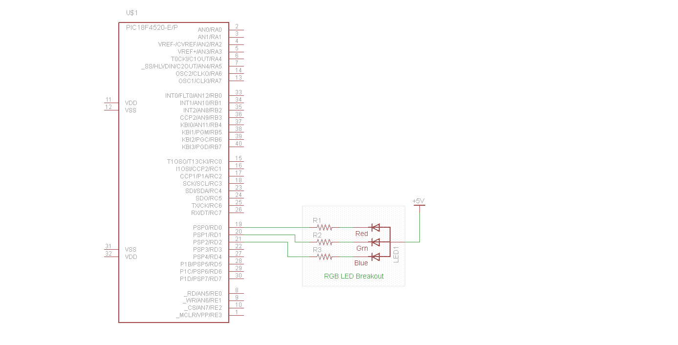
In this example we will connect an RGB led to our Pic 18F4520 Port D. We will then light the red, green and blue individually.
We will connect this up as follows
DO – RED LED
D1 – GREEN LED
D2 – BLUE LED
Lets see a simple schematic of this
Schematic
Code
This was written using mikroC Pro for PIC, a free evaluation version is available from http://www.mikroe.com/mikroc/pic/
[codesyntax lang=”c”]
/*
* Project name:
RGB led
*/

void main() {

TRISD = 0; // set direction to be output

do {
LATD = 0xFF; // Turn OFF LEDs on PORTB, common anode RGB LED
Delay_ms(200); // 1 second delay
LATD = 0xFE; // Turn ON RED LED
Delay_ms(200); // 1 second delay
LATD = 0xFF; // Turn OFF LEDs on PORTB, common anode RGB LED
Delay_ms(200); // 1 second delay
LATD = 0xFD; // Turn ON GREEN LED on PORTB
Delay_ms(200); // 1 second delay
LATD = 0xFF; // Turn OFF LEDs on PORTB, common anode RGB LED
Delay_ms(200); // 1 second delay
LATD = 0xFB; // Turn ON BLUE LED
Delay_ms(200); // 1 second delay
LATD = 0xFF; // Turn OFF LEDs on PORTB, common anode RGB LED
Delay_ms(200); // 1 second delay
} while(1); // Endless loop
}
[/codesyntax]
Links
PIC18F4520 PIC 8-bit RISC Development Evaluation Board +14 Accessory Modules
Pic mcu development board experimental board pic18f4520


