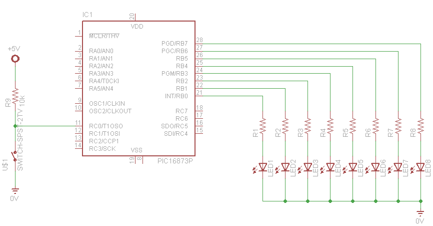
In this example we connect a push button switch to the first bit of PORT C (RC0) which will be configured as an input pin. The push button is connected to a 10k pull up resistor this means that the input pin is sitting at 5v when the switch is not pressed. When the switch is pressed this pin RC0 will be pulled to ground. In our code we will monitor for this and then switch on some LEDs when this occurs
There are 8 LEDs are connected to PORT B and a 470 ohm resistor is connected in series with each one.
You could of course only use 1 LED and resistor if you desired
Schematic
Code
This was written using Mplab XC 8
[codesyntax lang=”c”]
#define _XTAL_FREQ 4000000
// BEGIN CONFIG
#pragma config FOSC = HS // Oscillator Selection bits (HS oscillator)
#pragma config WDTE = ON // Watchdog Timer Enable bit (WDT enabled)
#pragma config PWRTE = OFF // Power-up Timer Enable bit (PWRT disabled)
#pragma config BOREN = ON // Brown-out Reset Enable bit (BOR enabled)
#pragma config LVP = OFF // Low-Voltage (Single-Supply) In-Circuit Serial Programming Enable bit (RB3 is digital I/O, HV on MCLR must be used for programming)
#pragma config CPD = OFF // Data EEPROM Memory Code Protection bit (Data EEPROM code protection off)
#pragma config WRT = OFF // Flash Program Memory Write Enable bits (Write protection off; all program memory may be written to by EECON control)
#pragma config CP = OFF // Flash Program Memory Code Protection bit (Code protection off)
//END CONFIG

#include <stdio.h>
#include <stdlib.h>
#include <xc.h>
/*
*
*/
int main(int argc, char** argv)
{
TRISB = 0x00;
TRISC0 = 1; //RD0 as Input PIN
do
{
if(RC0 == 0) //If the switch is pressed
{
__delay_ms(100); //Switch Debounce
if(RC0 == 0)//If the switch is still pressed
{
PORTB = 0x00; //LED OFF
__delay_ms(3000);
}
}
PORTB = 0xFF; //LED ON
}while(1);

return 0;

}
[/codesyntax]
Links


