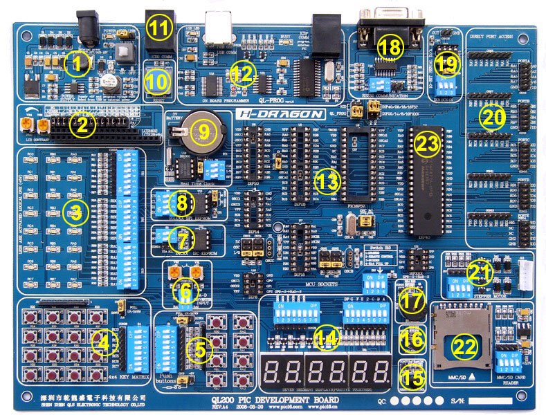
Pulse Width Modulation (PWM) is a technique used to control analog devices using digital signals.
It is widely used for motor speed control, LED dimming, and communication applications.
Most PIC microcontrollers include CCP (Capture/Compare/PWM) modules that allow precise PWM signal generation with minimal CPU intervention.
Understanding PWM in PIC Microcontrollers
A PWM signal consists of:
- Frequency: How often the signal repeats per second.
- Duty Cycle: The percentage of time the signal is HIGH within one period.
Formula:
Duty Cycle(%)=(Total Period/ON time)×100
Example:
- If a 1 kHz PWM signal has a duty cycle of 50%, it means the signal is HIGH for 0.5ms and LOW for 0.5ms.
CCP Module Overview
The CCP (Capture/Compare/PWM) module in PIC microcontrollers supports PWM mode, where it generates a periodic pulse with adjustable duty cycle.
CCP Registers for PWM Mode
| Register | Purpose |
|---|---|
| CCP1CON | Configures CCP module for PWM mode |
| CCPR1L | Holds the 8 Most Significant Bits (MSBs) of the duty cycle |
| CCP1CON<5:4> | Holds the 2 Least Significant Bits (LSBs) of the duty cycle |
| TMR2 | Timer 2 provides the time base for PWM |
| PR2 | Defines the PWM period |
| T2CON | Configures Timer 2 (prescaler and enable bit) |
PWM Frequency Calculation
The PWM frequency is determined by the PR2 register and the Timer 2 prescaler.
PWM Period=(PR2+1)×4×Tosc×Prescaler
PWM Frequency = 1/PWM Period
Where:
- Tosc=1FoscT_{osc} = \frac{1}{F_{osc}} (Clock cycle time)
- FoscF_{osc} is the oscillator frequency
- PR2 is an 8-bit register (0 to 255)
- Prescaler can be 1, 4, or 16
Example Calculation
If:
- Fosc=8MHzF_{osc} = 8MHz
- PR2 = 124
- Timer2 Prescaler = 16
PWM Period = (124+1)×4 × 1/8MHz ×16
PWM Frequency = 1/(125 × 4 × 1/8MHz × 16)
PWM Frequency = 1kHz
Setting PWM Duty Cycle
The PWM duty cycle is controlled using CCPR1L and CCP1CON<5:4> bits.
Duty Cycle (10-bit)=(CCPR1L:CCP1CON<5:4>)×Tosc×4\text{Duty Cycle (10-bit)} = \left( CCPR1L:CCP1CON<5:4> \right) \times T_{osc} \times 4
- CCPR1L holds the upper 8 bits.
- CCP1CON<5:4> holds the lower 2 bits.
Example
For 50% duty cycle on a 1 kHz PWM:
Duty Cycle (10-bit)=125×42=250\text{Duty Cycle (10-bit)} = \frac{125 \times 4}{2} = 250
- CCPR1L = 0x3E (62 in decimal)
- CCP1CON<5:4> = 0b10
Implementing PWM on PIC Microcontroller
We will configure PWM using CCP1 module on a PIC16F877A to control LED brightness.
Hardware Requirements
- We used a PIC16F877A microcontroller
- 8 MHz external crystal
- LED with resistor (330Ω)
- Power supply (5V)
Circuit
- PWM output is on RC2 (CCP1 pin).
- The LED is connected to RC2 with a 330Ω resistor.
PIC PWM Code Example
We used MPLAB X with the XC8 compiler for this example
#include <xc.h>

// Define Configuration Bits (For PIC16F877A)
#pragma config FOSC = XT // Oscillator Selection
#pragma config WDTE = OFF // Watchdog Timer Disabled
#pragma config PWRTE = OFF // Power-up Timer Disabled
#pragma config BOREN = ON // Brown-out Reset Enabled
#pragma config LVP = OFF // Low Voltage Programming Disabled

#define _XTAL_FREQ 8000000  // Define clock frequency (8MHz)

void PWM_Init(unsigned int frequency);
void PWM_DutyCycle(unsigned int duty);

void main() {
    TRISC2 = 0;  // Set CCP1 (RC2) as output
    PWM_Init(1000);  // Initialize PWM with 1 kHz frequency

    while(1) {
        PWM_DutyCycle(512);  // Set 50% duty cycle (512 out of 1023)
        __delay_ms(1000);

        PWM_DutyCycle(256);  // Set 25% duty cycle (256 out of 1023)
        __delay_ms(1000);

        PWM_DutyCycle(768);  // Set 75% duty cycle (768 out of 1023)
        __delay_ms(1000);
    }
}

// Function to Initialize PWM
void PWM_Init(unsigned int frequency) {
    unsigned int PR2_value;

    PR2_value = (_XTAL_FREQ / (frequency * 4 * 16)) - 1;
    PR2 = PR2_value;  // Set PR2 for the required PWM frequency

    CCP1CON = 0x0C;  // Configure CCP1 as PWM mode
    T2CON = 0x04;  // Enable Timer2 with Prescaler = 1

    // Start Timer2
    TMR2 = 0;
    TMR2ON = 1;
}

// Function to Set PWM Duty Cycle (0 to 1023)
void PWM_DutyCycle(unsigned int duty) {
    CCPR1L = duty >> 2;  // Upper 8 bits
    CCP1CONbits.DC1B = duty & 0x03;  // Lower 2 bits
}
Explanation
- Initialize PWM (PWM_Init())
- Configures CCP1 module in PWM mode.
- Calculates PR2 value for the required PWM frequency.
- Enables Timer2 with an appropriate prescaler.
- Set Duty Cycle (PWM_DutyCycle())
- Converts 10-bit duty cycle value into 8-bit (CCPR1L) and 2-bit (CCP1CON<5:4>) values.
- Main Loop
- Changes LED brightness by setting different duty cycles (25%, 50%, 75%).
Summary
| Step | Description |
|---|---|
| 1. Configure CCP1 | Set CCP1CON = 0x0C for PWM mode |
| 2. Set Timer2 | Configure T2CON for PWM timing |
| 3. Calculate PR2 | Use formula to determine PR2 for desired frequency |
| 4. Set Duty Cycle | Adjust CCPR1L and CCP1CON<5:4> |
| 5. Enable PWM | Start TMR2 |
Applications of PWM
- Motor Speed Control
- LED Brightness Control
- Analog Signal Generation
- Audio Signal Processing
This tutorial covers everything needed to generate PWM signals using PIC CCP module


